Your Cart (0)

 CONTACT US
 CATALOGS
Ideal Tridon Group Blog.
How to Install an Ideal Tridon Heavy Duty No-Hub Coupling
March 16, 2023
Recommended practice for installation of Super Heavy Duty Green Shield & Heavy Duty Yellow Shield No-Hub Couplings
This is the recommended practice for installation of Super Heavy Duty Green Shield & Heavy Duty Yellow Shield No-Hub Cast Iron Pipe Couplings manufactured by Ideal Clamp Products, Inc.
.png)
Step 1: Cut pipe ends as squarely and smoothly as possible.
Step 2: Check coupling and gasket for foreign material and clean if necessary.
Step 3: Insert gasket over pipe or fitting until end of pipe or fitting butts against the gasket's integrally molded shoulder.
Step 4: Slide the coupling assembly over the other pipe or fitting to be joined.
Step 5: Insert the second pipe or fitting into the gasket until both ends of pipe or fittings butt against the integrally molded shoulder in the center of the gasket.
Step 6: Slide the coupling assembly into position, centered over the gasket. At this point, it is recommended to hand tighten the clamp and shield assembly with a wrench.
Final tightening is described below.
Step 7: Use a preset, or preferably, a dial indicating type torque wrench and tighten clamps to 80 inch-pounds of torque using the procedure below.
For coupling sizes 1 ½", 2", 3", and 4", which have four clamps:
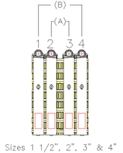
Step 8: First, the inner clamps "A" are to be tightened alternately in 20 lbf-in increments until the recommended 80 lbf-in is reached.
Step 9: Then the outer clamps, "B", are tightened alternately in 20 lbf-in increments until the recommended 80 lbf-in is reached.
Note: When O.D. difference between pipe and fitting is noticeably different, the torque pattern is recommended 1-3, 2-4. This assumes min. 0 pipe is under 1 & 2 as shown. If not, reverse sequence.
For coupling sizes 5", 6", 8", and 10", which have six clamps:
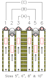
Step 8: First, the inner clamps "A" are to be tightened alternately in 20 lbf-in increments until the recommended 80 lbf-in is reached.
Step 9: Next, the middle clamps "B" are to be tightened alternately in 20 lbf-in increments until the recommended 80 lbf-in is reached.
Step 10: Finally, the outer clamps "C" are to be tightened alternately in 20 lbf-in increments until the recommended 80 lbf-in is reached.
Note: When O.D. difference between pipe and fitting is noticeably different, the torque pattern is recommended 1-4, 2-5, 3-6. This assumes the min. 0 pipe is under 1, 2, & 3 as shown. If not, reverse sequence.
For installation details inside and outside building, see CISPI 310.
HOW DO I KNOW WHEN MY CLAMP IS FULLY TIGHTENED?
Our market exclusive Visual Torque Indicator offers instant proof of proper installation, taking the guesswork out of the equation! When the clamp band falls within the hatched area, you know that your no-hub coupling has been properly tightened.
This reduces inspection time and allows for more flexibility in your schedule.
Ideal Tridon created the Visual Torque Indicator to assist with field installations and always recommends using a torque wrench to install no-hub couplings per the instructions above.